ラズベリーパイ2
FreeBSD
自宅サーバをラズベリーパイ4で作るため、
余ったラズベリーパイ2で
IOT(鯖4猫)を作ります。
2021年
9月23日
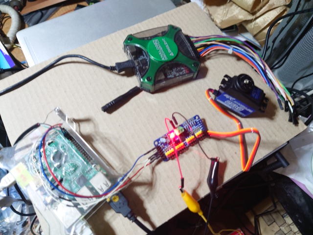
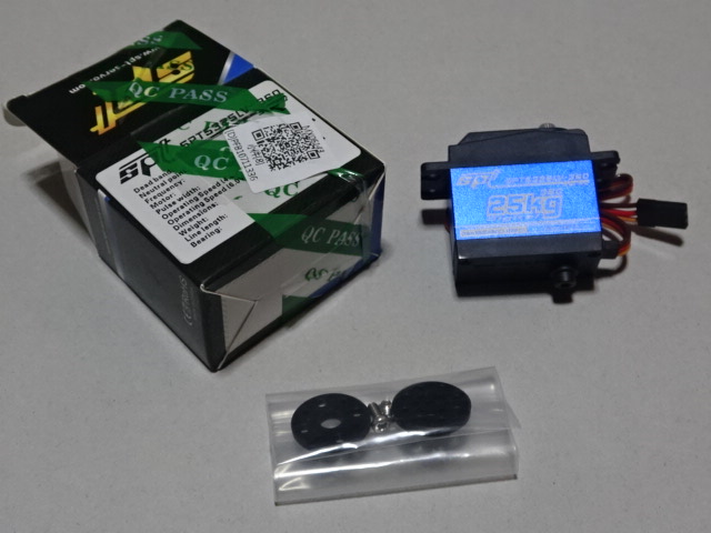
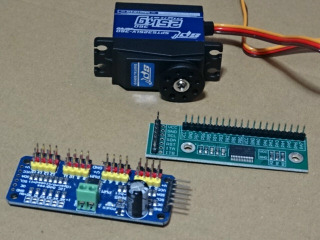
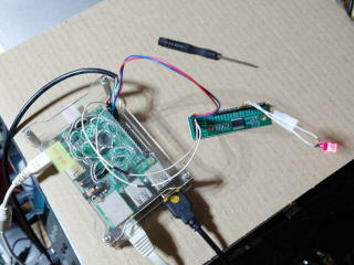
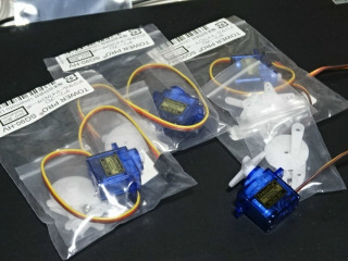
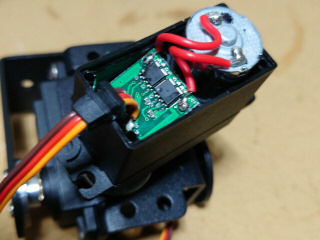
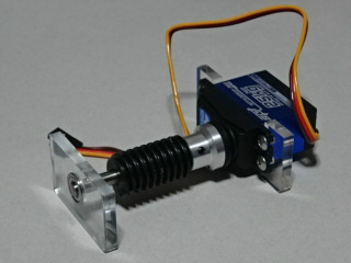
こちらはアマゾンで購入のI2CのPWMとGPIO基板です。PWMに接続する連続回転のサーボモータもいっしょに購入しました。自宅サーバをラズベリーパイ4にすると、ラズベリーパイ2が余ってしまうので、ネットワーク接続のIOT用に購入しました。ラズベリーパイのFreeBSDはI2Cを有効にするだけで使えるようになるはずです。ラジコンのサーボを停止状態にするには1.5mmSecの幅のパルスを出し続ければ良いのですが、省電力のためには所定の位置まで回転後に電源を切るか脱力したいです。これはPWMボードが動作後に実験して確認します。
10月19日
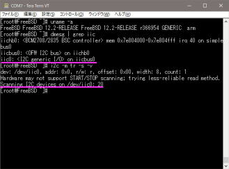
アパート作業です。アマゾンで購入したI2CのGPIO基板の動作確認をラズベリーパイ2で行います。FreeBSD側のI2Cコントローラはiic0が1つ出てくるのが正解です。ボードのコントローラはmcp23017で、i2cコマンドでスキャンするとアドレス20が出てきます。
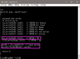
早速、ここのページを参考にポートAを出力、ポートBを入力に初期化し、ポートAに55を出力、ポートBから値を入力するプログラムを作成しました。入力はプルアップなので、何もしなければFFが読み出され、端子をGNDとショートすれば値が変わります。ポートAはテスタで確認し、動作良好です。
10月19日
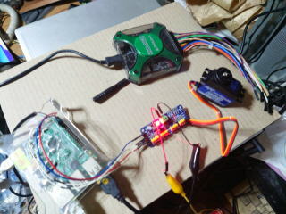
アパート作業です。アマゾンで購入したI2CのPWM基板の動作確認をラズベリーパイ2で行います。i2cコマンドでスキャンすると、データシートの通りアドレス40が出てきます。ここにPIC用のサンプルコードがあるので参考にします。先日のmcp23017用のプログラムに参考ページの初期部をマージしてプログラムを作成しました。予めパルス幅が制御できることをアナログディスカバリで確認した後、実際に連続回転サーボモータを接続して動作確認しました。幅1.5mSecを中心にして、正転、逆転の回転数が制御できることを確認しました。
10月24日
TK80/BSのシンセシステムを復活/拡張したい〜その65から分岐しました。
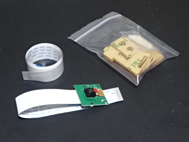
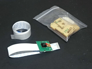
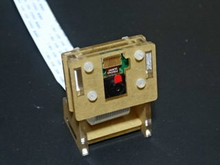
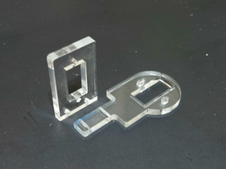
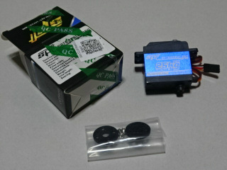
この週末は日曜のみの作業です。アマゾンで購入の小型連続回転サーボモータと旧バージョンのラズベリーパイ用カメラです。カメラは以前に購入済みですが、ケーブルが短いのでアマゾンで延長ケーブルを探していた所、カメラに50cmのケーブルが付属していて1580円だったので購入しておきました。
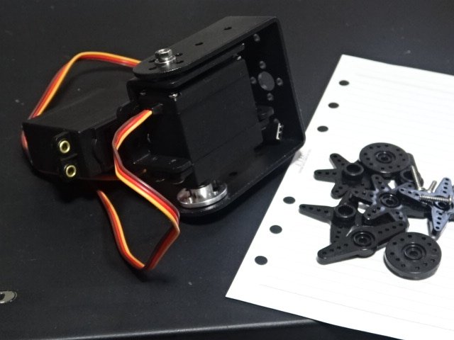
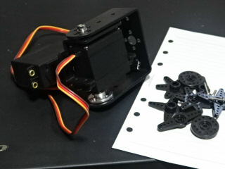
こちらも、アマゾンで購入のサーボモータ付きジンバルです。上のカメラを取り付ける予定です。
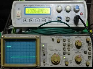
小型の連続回転サーボモータ、ジンバルのサーボモータとも、アナログディスカバリの代わりにDDSファンクションジェネレータを使って動作確認を行いました。アナログディスカバリはアパートに忘れてきました。動作は良好です。ファンクションジェネレータのデューティ調整では細かい制御できないので、デューティは固定して、周波数でパルス幅を調整すれば、サーボモータを制御できます。
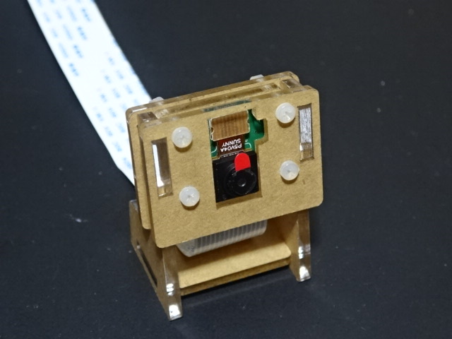
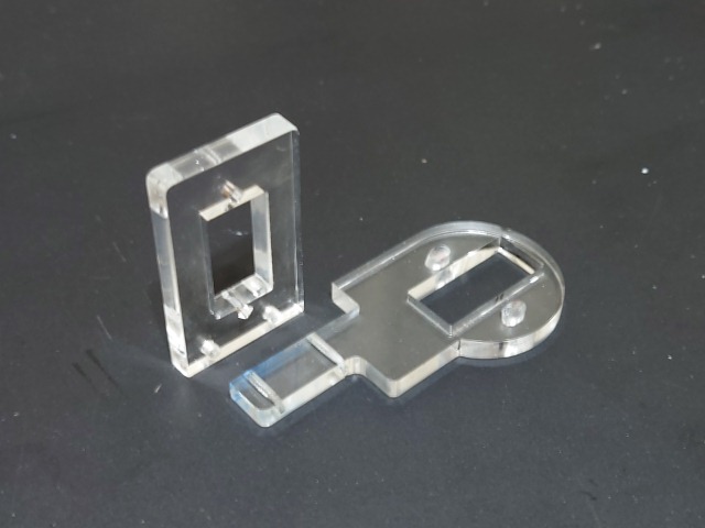
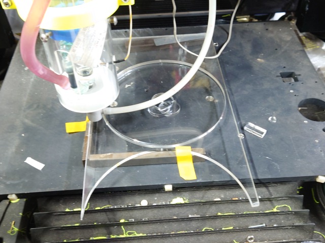
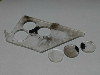
カメラに付属のアクリル製のスタンドを仮組みしてみました。
10月30日
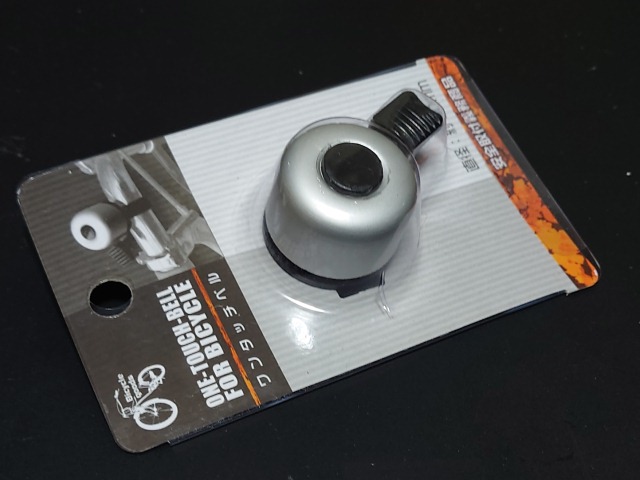
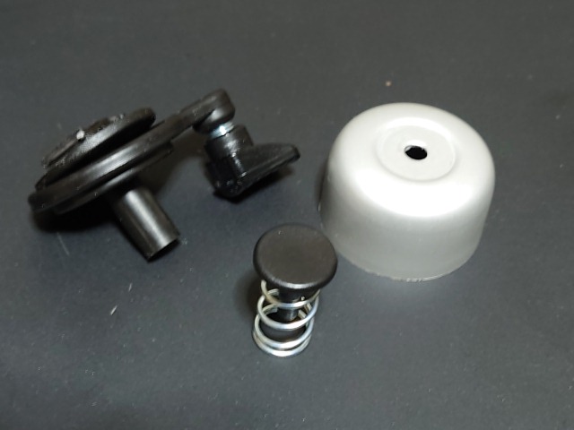
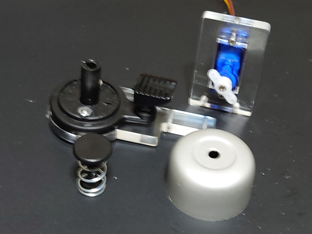
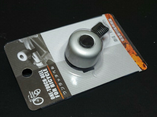
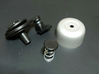
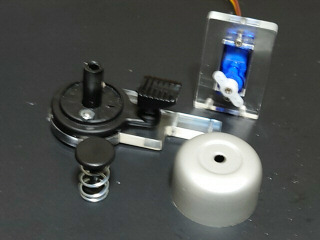
この週末は5連休になりました。100円ショップの自転車用のベルです。早速、分解してみます。1回づつ鳴るタイプです。
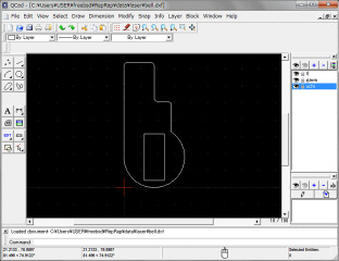
ベルを採寸して、QCADで図面を入力します。

5mmのアクリルからサーボモータのステーを作製しました。
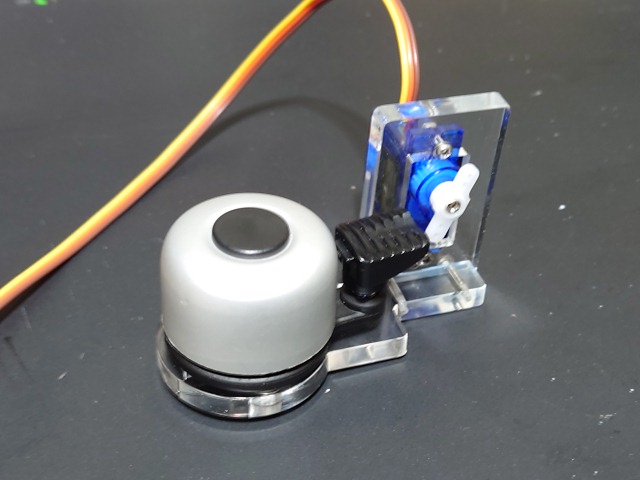
早速、小型連続回転サーボモータを取り付けて組み立てます。
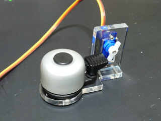
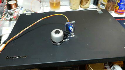
パルス幅をファンクションジェネレータで駆動した動画を再生します。
10月31日
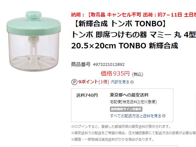
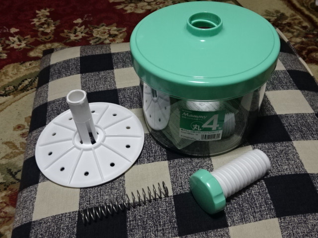
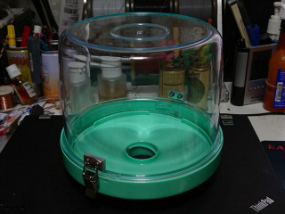
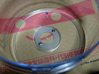
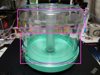
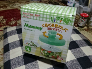
ケース本体は近所のスーパマーケットで売っていた即席漬物器4リットルを使います。
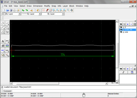
ふたをケース本体に固定するために、パッチン止めのスペーサの図面をQCADで作成します。繋げて作り、後で4分割します。ケースの直径は約190mmです。
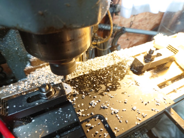
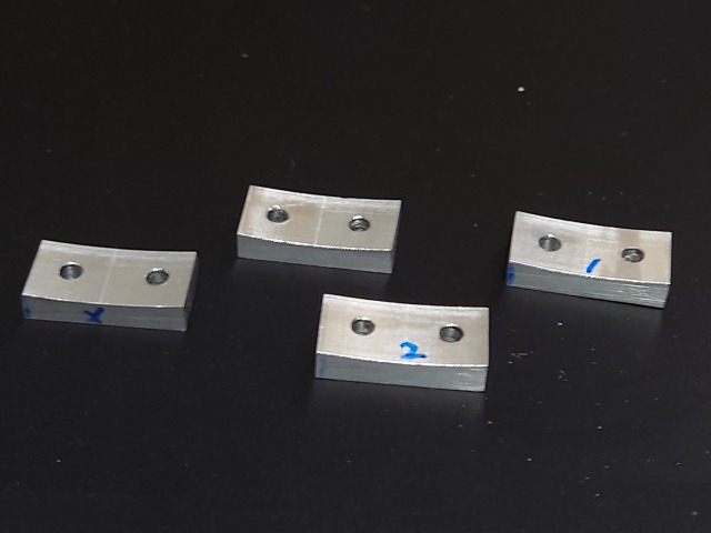
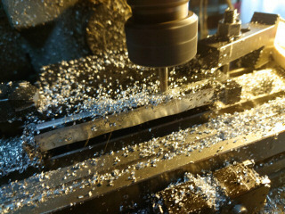
パッチン止めのスペーサを12.7mmのアルミ板からCNCで作製します。

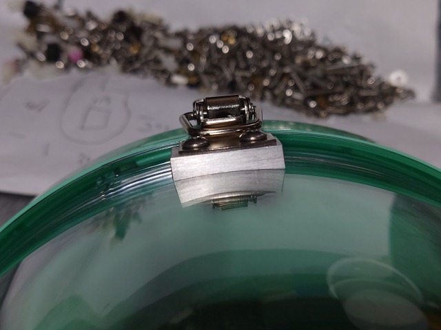
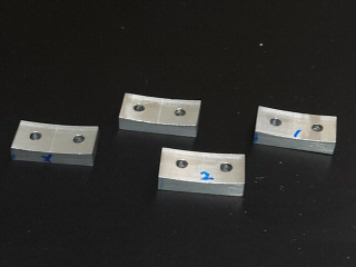
パッチン止めのスペーサが4個完成しました。早速取り付けてみます。190mmのR部もちょうど良いようです。
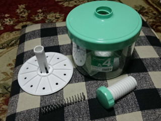
パッチン止めは2ヶ所で固定します。即席漬物容器のスプリングと円盤は取り外し、上下逆さに使います。
11月1日
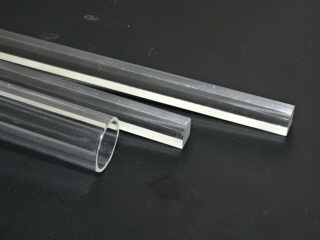
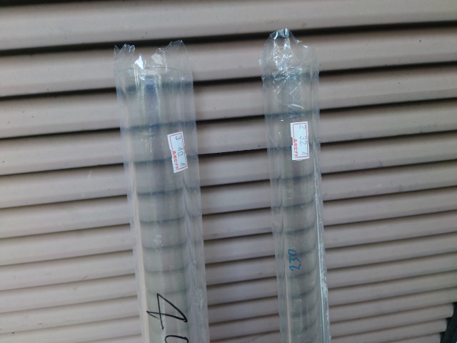
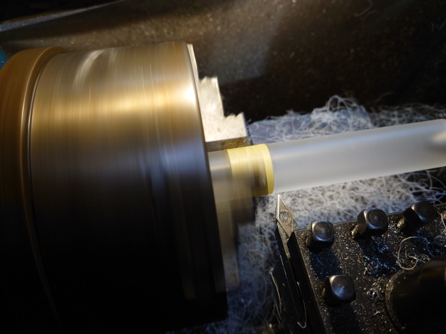
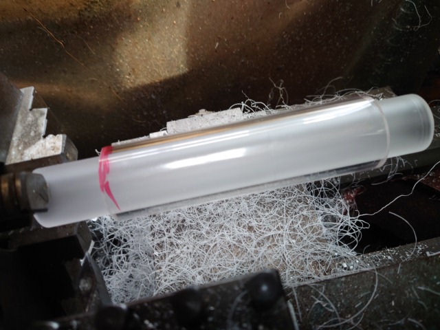
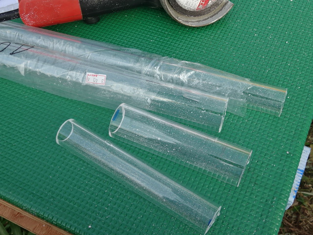
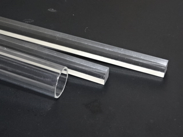
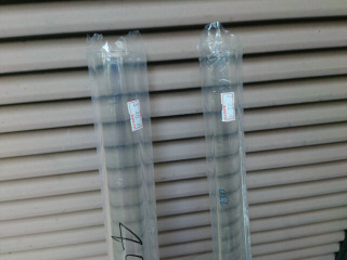
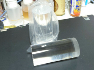
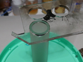
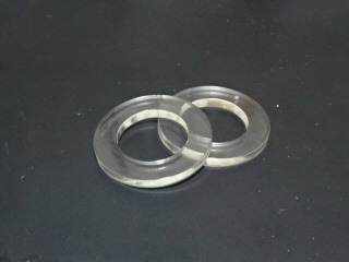
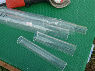
アクリル専門通販でアクリルパイプ2種を購入しました。長さは定尺の1mです。外径40mmと32mmでアクリルの厚みは4mmです。計算上は40mmに32mmが丁度入るはずですが、残念ながら、公差があり入りません。
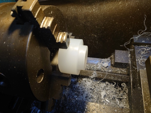
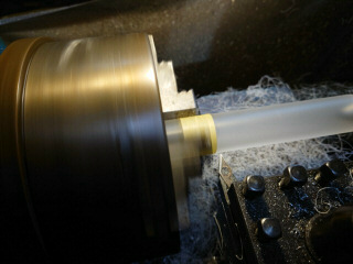
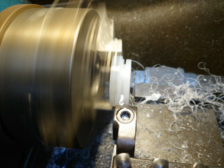
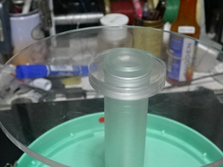
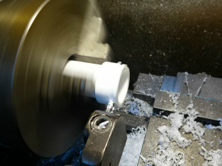
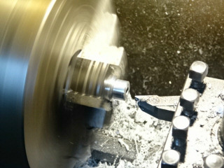
32mmの外径を少し削って、40mmに32mmが入るようにします。32mmが固定センタで、40mmの方が回転センタです。

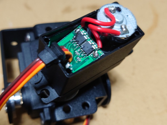
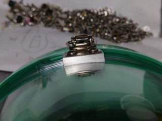
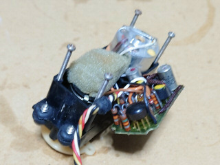
サーボモータの今昔を比べてみます。左は2軸ジンバルに付属していたMG996サーボの制御基板です。コントローラが1個とFETが2個の3チップ構成です。右は昭和50年代のエンジン飛行機用のサーボです。今ではPCの周辺機器を作っているロジテック製です。トランジスタやオペアンプ、抵抗などがてんこ盛りです。CANケースのトランジスタが時代を感じさせます。半固定も複数あり、調整も必要です。
11月2日
こちらはヤフーショッピングで購入したスペーサ等を作製するための50mmのアクリル棒です。長さは110mmで2個特価で1280円でした。ただ中国からの発送なので時間が掛りました。
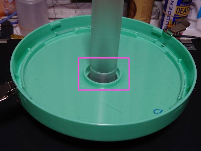
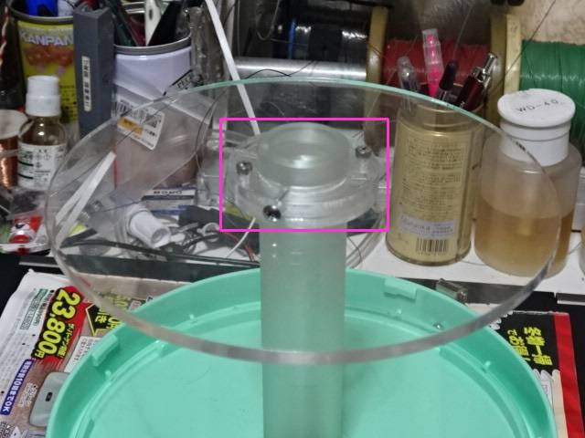
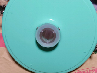
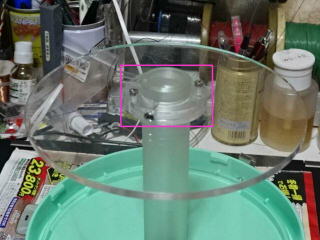
ケースの上部に取り付ける固定センタ用のホルダを端材のポリプロピレン樹脂で作製しました。3mmのネジ2ヶ所で固定しました。
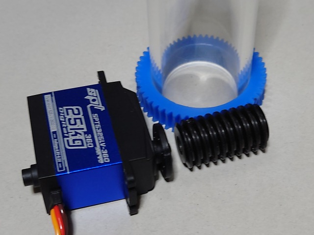
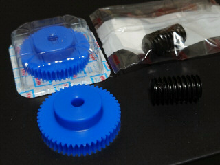
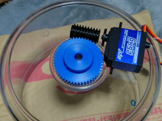
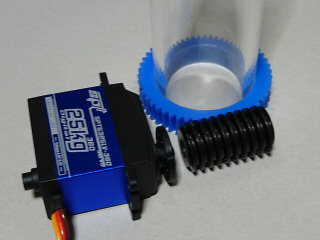
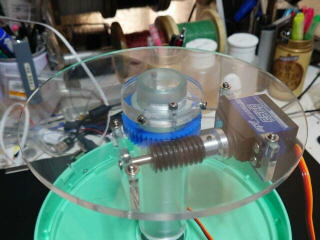
モノタロウで購入したモジュール1のウォームギアが到着しました。歯数50で、直径は53mmです。連続回転サーボと組み合わせて、部品の位置を仮組してみます。
ケー
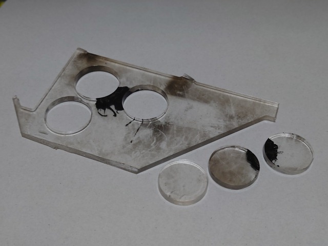
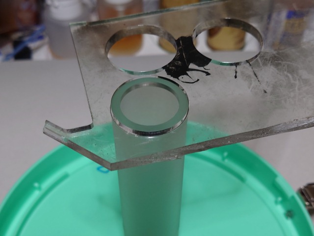
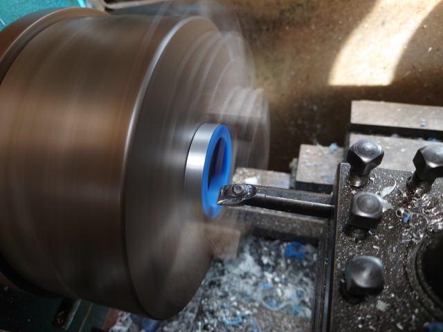
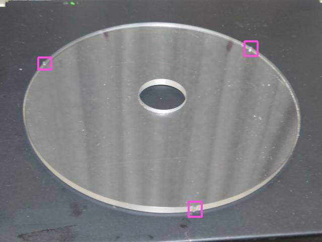
ス内に入れるベース板を作製します。外径を少し削った32mmの固定センタにキッチリ固定する必要があるので、内側の丸加工を予め調整します。端
材で試し切りを行い、丁度良い寸法を調べました。レーザの直径を0.7mm位で考えると良いようです。丸加工は半径にして0.35mm位小さく図面を書く必
要があります。
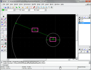
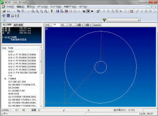
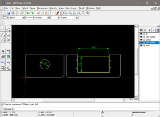
固定センタの直径を31.3mmにしてQCADで下側ベース板の図面を入力します。その後、HeeksCNCでGコードを生成して、NCVCで確認します。
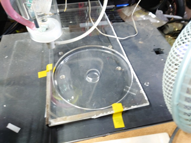
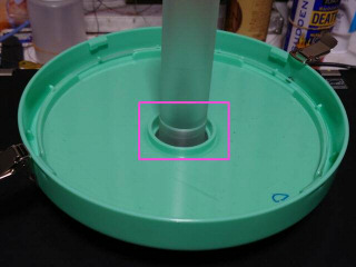
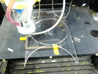
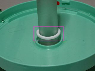
早速、5mm厚のアクリル板から下側ベース板を切り出します。直径が約190mmでレーザ加工機ギリギリで加工できるサイズです。透明で見にくいですが、下側ベース板をふたに仮固定してみます。丁度良いようです。

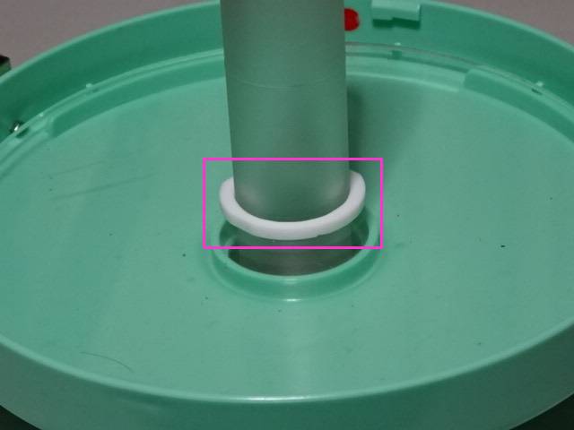
固定センタをふたに固定するスペーサを端材のポリプロピレンで作製します。3か所でネジ止めして固定します。

11月3日
ウォームホイールの内径を固定センタの32mmに広げて丁度はまるように削ります。はまっているだけなので、後でピンを打って固定します。

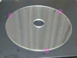
ウォームホイールを駆動する連続回転サーボモータを固定する上側ベース板を5mmのアクリル板から切り出します。上下ベース板とも3か所に突起を付けて、ケースの内側と接触するようにします。
透明で見にくいですが、固定センタに上下のベース板を仮止めしたケースが完成しました。
11月13日
ケースに使っている簡易漬物容器が近所のスーパーマーケットに置いて無くなってしまったので、アマゾンで購入しました。早速、内側のプレートを取り外しました。
11月14日
ウォームホイール駆動用のサーボモータを取り付ける上側ベース板の固定リングを5mmのアクリルから作製しました。2枚重ねて使います。
11月20日
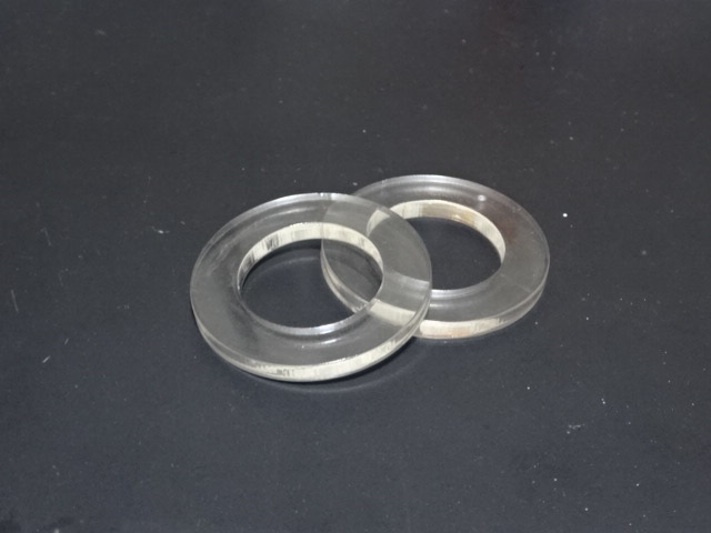
2個目の固定センタと回転センタを切り出しました。
11月22日
追加の連続回転サーボモータをアマゾンで購入しておきました。
先週作製した固定リングをジクロロメタンで2枚貼り合わせて、上側ベース板に固定し、固定センタにネジ止めします。
回転センタの荷重を受けるために、3mm厚のテフロン樹脂でワッシャを作製しました。
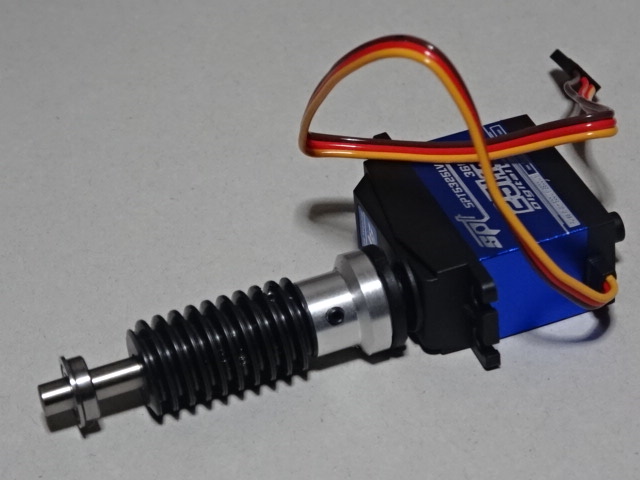
続いて、連続回転サーボのホーンと6mmのシャフトを連結するアダプタをアルミで作製しました。シャフトとウォームギア、ベアリングを仮り組みしてみます。良いようです。

5mm厚のアクリルからベアリングホルダとサーボモータホルダを作製します。ベアリングの内径は実際には少し小さくしておきます。
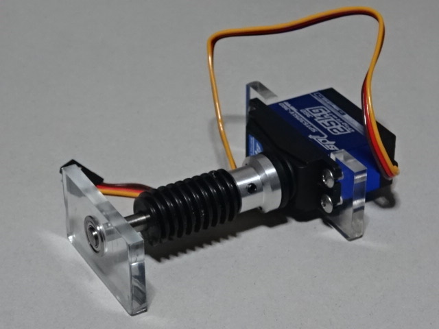
レーザ加工機で作製したベアリングホルダにベアリングを圧入してウォームギア駆動部を組み立てます。
組み立てたウォームギア駆動部を上側ベース板に取り付けます。固定用の穴は長穴にして、ギアの嚙み合わせが外せるようにしておきます。
11月28日
以前にアクリルパイプを購入した通販サイトで10mmの角棒と外径24mm(板厚1.5mm)のパイプを追加で購入しました。長さは定尺の1mです。