削り出しカーボン11/29号
その12:ラジアルマスタのカーボンレバーアダプタ作製
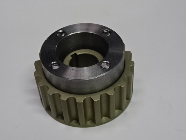
ベルトプーリのSSTの作製
燃調が濃い件の調査
2023年
5月14日
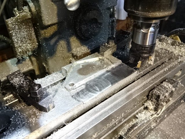
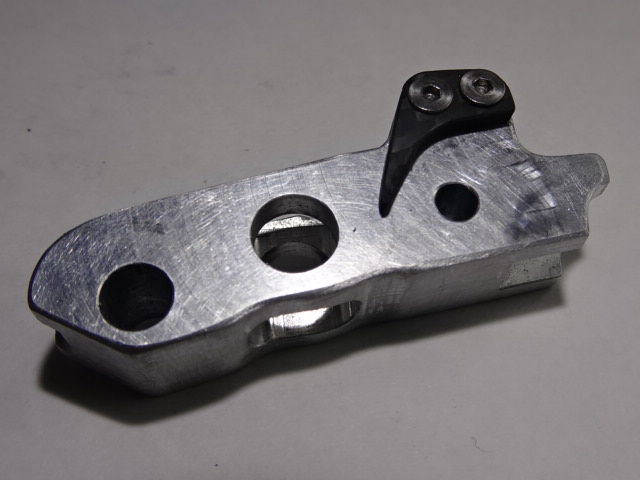
アリエクスプレスで購入した50mmのチップエンドミルで20mmのジュラルミンを16mmに削ります。

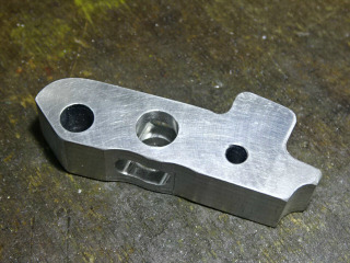
2mmの切り込みで9回切削してアダプタを切り出します。
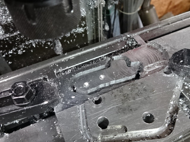
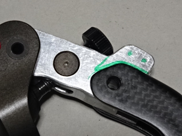
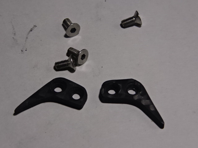
穴開けと調整ノブとカーボンレバーのストッパ部の後加工を行います。
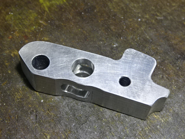
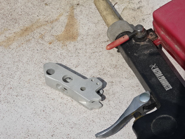
アダプタほぼ完成しました。
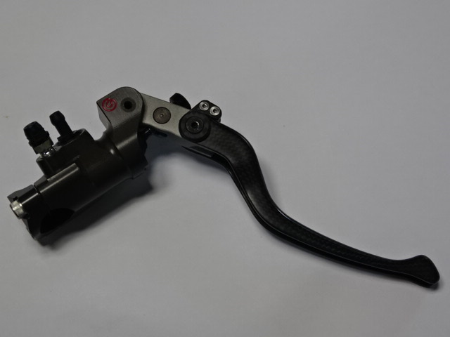
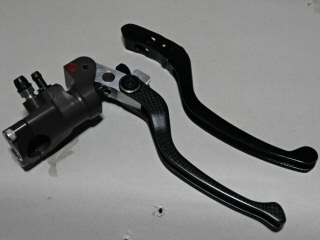
ラジアルマスタをアダプタを介して接続してみます。良いようです。この後、軽量加工と仕上げを行います。ラジアルマスタにはストップランプのスイッチが無いので工夫して取り付ける必要があります。
5月15日
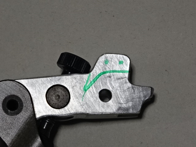
アダプタは軽量加工、微調整を行いました。カーボンレバーのストッパを作製します。
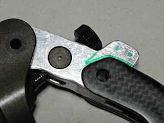
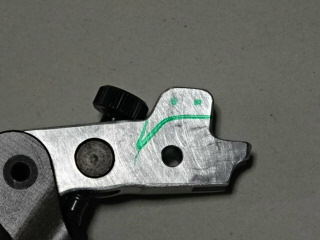
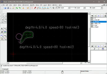
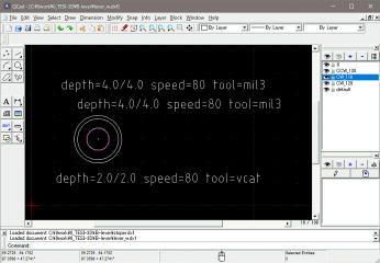
qcadにストッパの図面を入力しました。
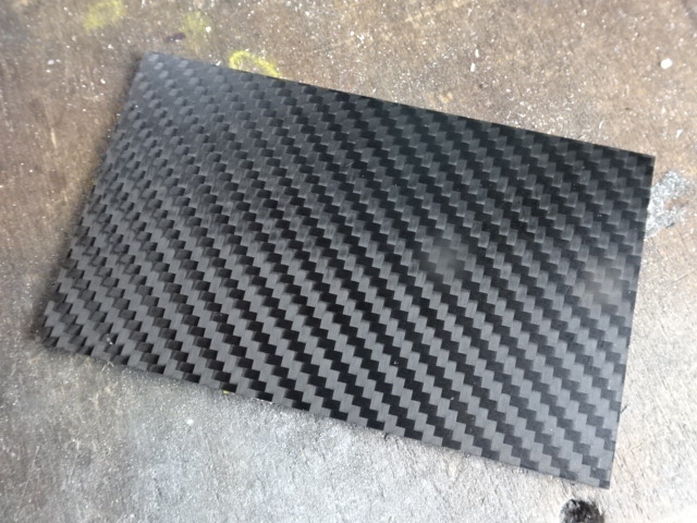
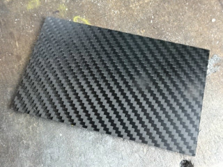
アマゾンで購入の3mm厚の綾織のカーボン板が到着しました。
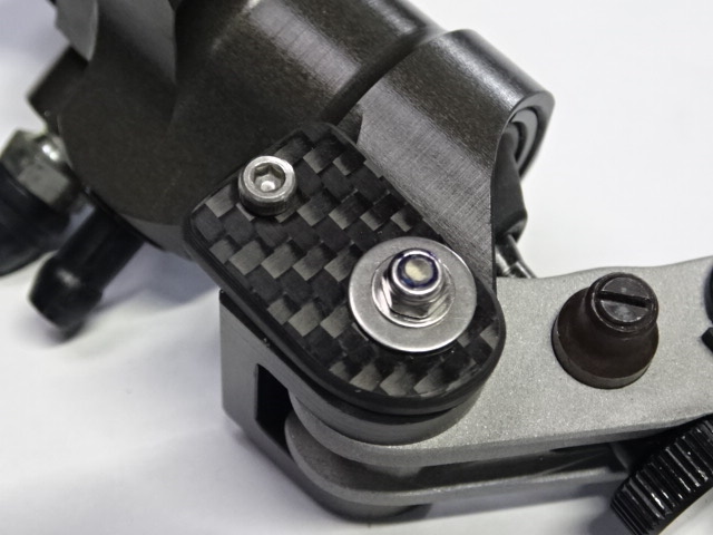
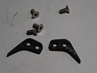
カーボン板からストッパをCNCフライスで切り出しました。アダプタには3mmでネジ切りをして、以前ホームセンタで購入したおいたステンレスのキャップサラネジで取り付けました。
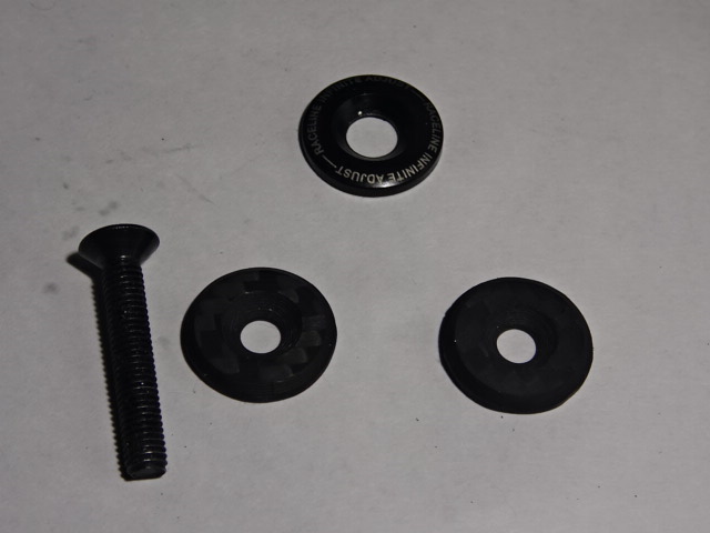
続いて、直径18.4mmのワッシャを作製します。qcadに図面を入力します。
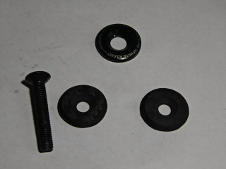
CNCフライスでワッシャを切り出しました。外周は45度のVカットエンドミルで面取りしました。上がカーボンレバーに付いていたオリジナルのアルミワッシャです。
5月16日
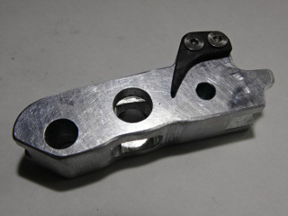
アダプタをサンドブラストしました。
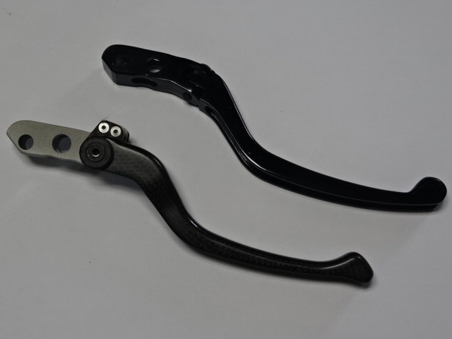
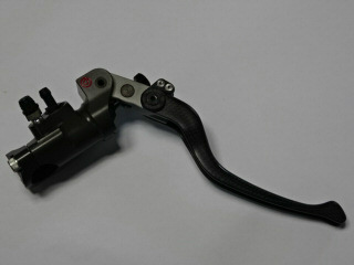
アダプタにストッパを付けてカーボンレバーと接続します。上がブレンボのオリジナルのレバーです。
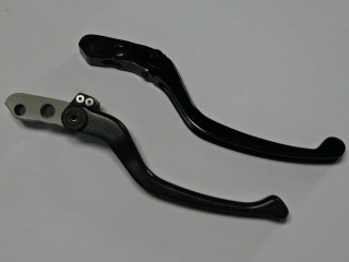
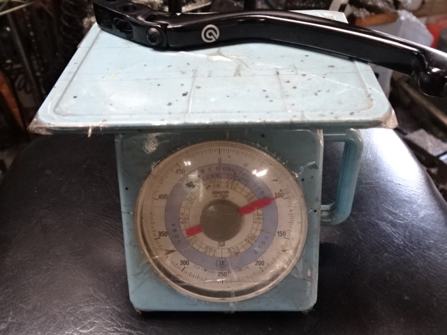
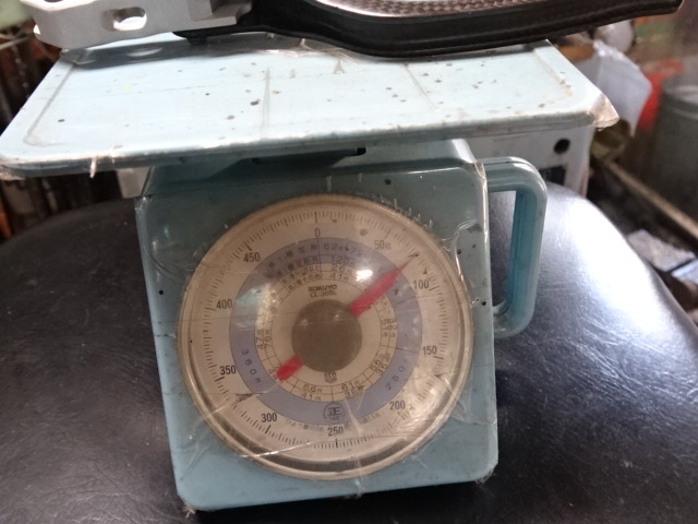
オリジナルは約90g、作製したカーボンレバー+アダプタは約70gでした。
接続アダプタ完成です。後はストップランプスイッチの追加です。
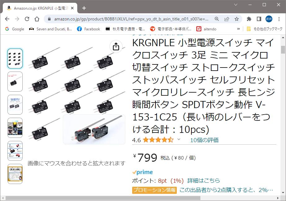
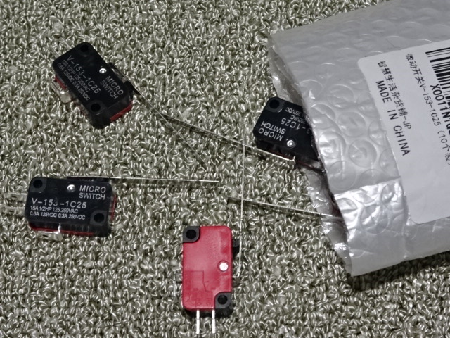
ストップランプ用のマイクロスイッチはアマゾンで発注しておきました。
5月16日
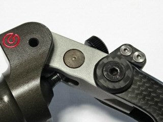
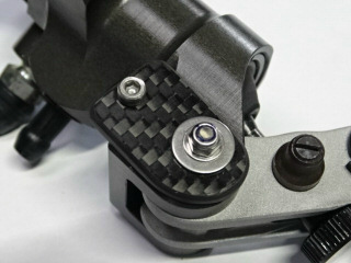
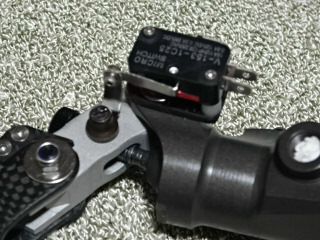
ストップランプスイッチをラジアルマスタに取り付けるベース板を3mm厚のカーボン板で作製しました。上のスイッチは手持ちのもので単極単投なので使えませんが、寸法の確認はできます。
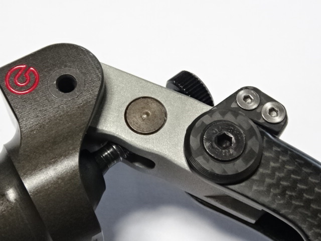
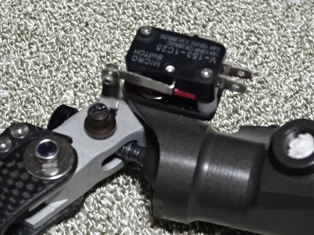
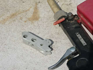
取り付けはレバービボットの中空穴を使います。左のキャップボルトは回り止めです。このベース板にスイッチを取り付けます。
5月19日
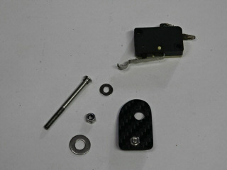
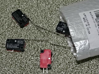
アマゾンで購入のマイクロスイッチが到着しました。なぜか、裏側は赤でした。
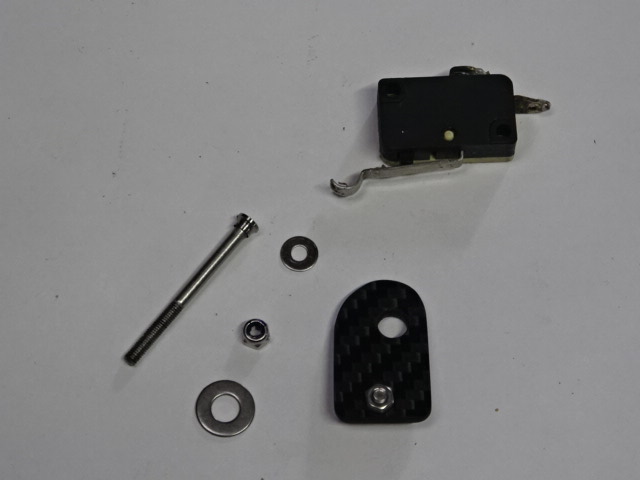
早速、ベース板に取り付けました。スペーサでベース板の固定ナット分の高さを浮かせました。スイッチレバーはL字に加工して、レバーの角度調整ナットと接触させます。単極双投なのでブレーキを掛けたときに通電する端子を使います。
5月23日
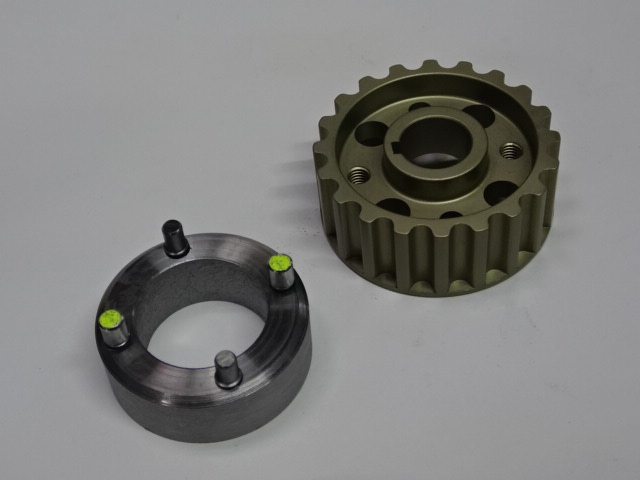
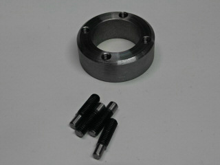
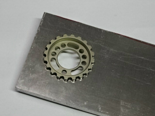
ベルトプーリSST作製の続きです。駆動側の回り止めは以前に作製したリングにピンを立てました。4ヶ所に5mmの穴開けをして6mmのタップでネジ切り、6mmの12.9ボルトを加工してピンを作製しました。アルミプーリ側に6mmのネジが2ヶ所切ってあるので、ピン2本は5mmに削りました。
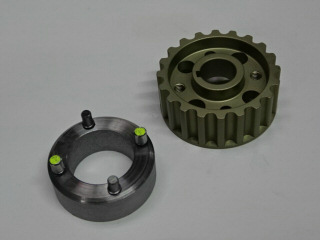
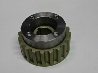
アルミプーリに勘合しました。ハンドル部はテージが戻って来てから作製します。
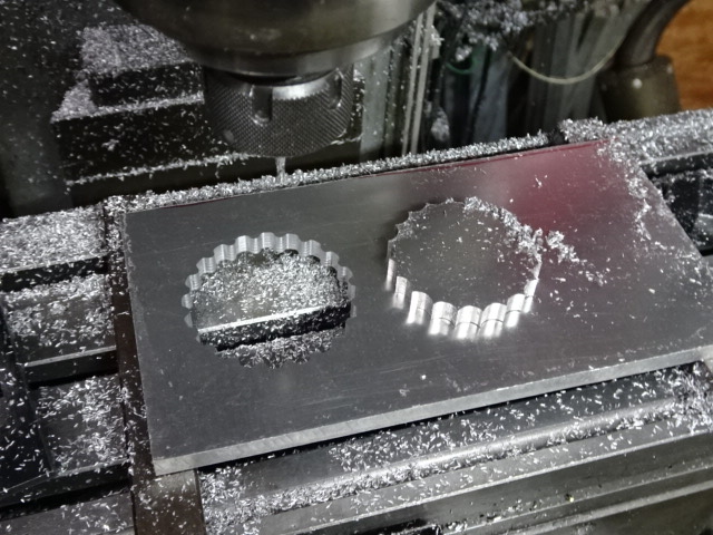
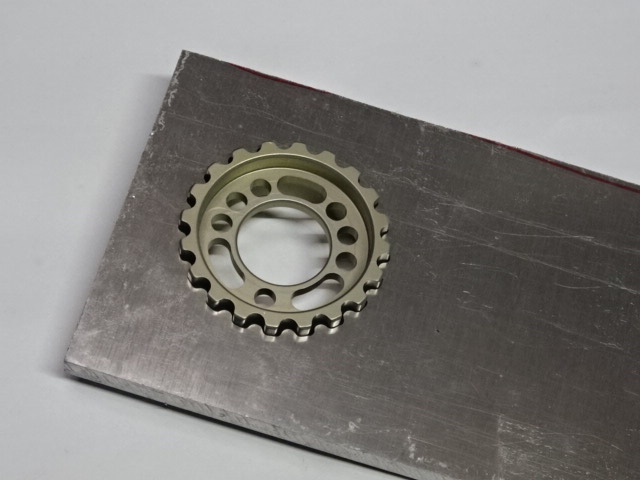
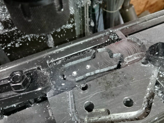
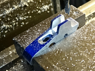
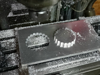
カムシャフト側の回り止めは8mmのジュラルミン板で内側のみ切削しました。アクリルで試し切りをした図面を修正して切り込みを1.5mmにして、6回切削しました。外形はテージが戻って来てから作製します。
5月31日
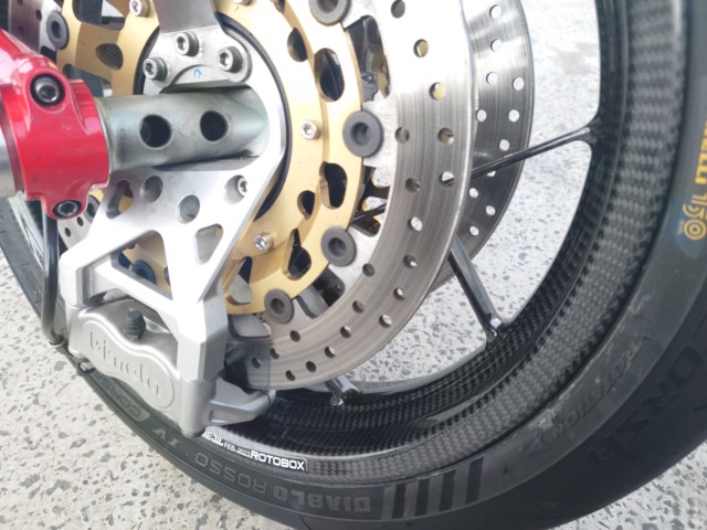
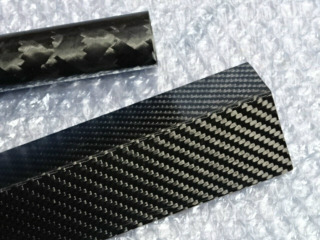
ebayで3月に購入したL字のカーボンロッドがやっと到着しました。上は同じ売り主から間違って購入して閉まったパイプです。サイズが長すぎで一度売り主の所に戻ってしまったのが遅れた原因のようです。スロベニアからですが、ホイールのロトボックスもスロベニアでした。タンクの固定用のステーとオイルクーラを吊り下げステーをカーボンに交換する予定です。
6月4日
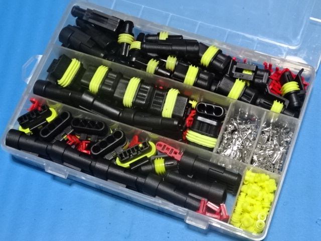
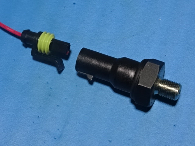
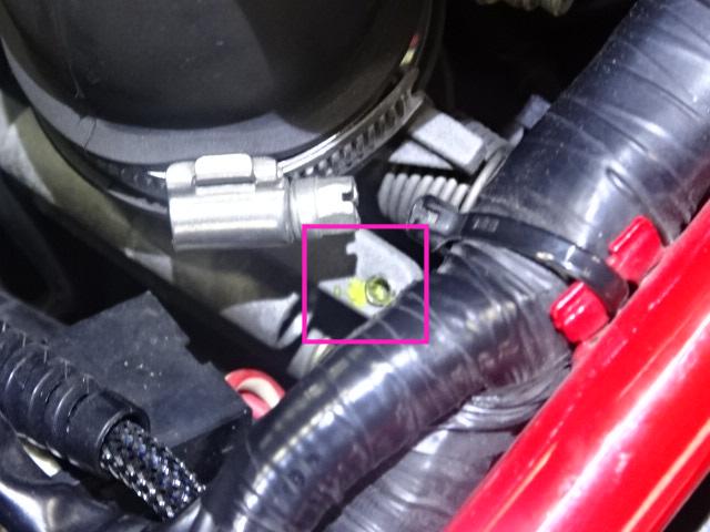
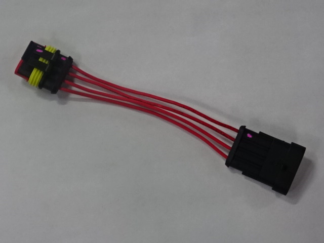
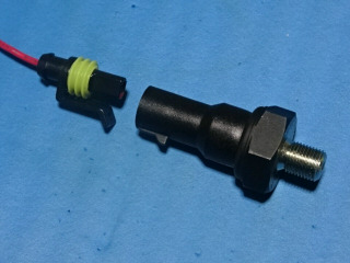
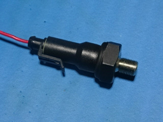
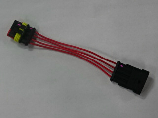
燃調が濃い件のセンサ接続用コネクタをアマゾンで購入しました。タイコのスパーシール(防水コネクタ)の互換品です。セットで1600円位で買えます。
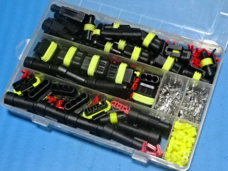
1極の油圧スイッチ用を圧接して試作しました。価格は安いですが、問題無く使用できます。
6月5日
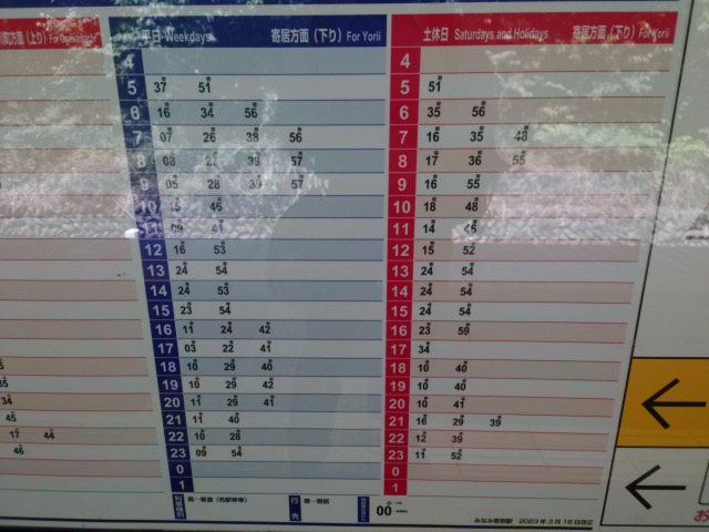
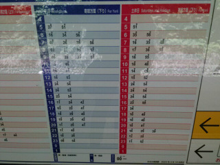
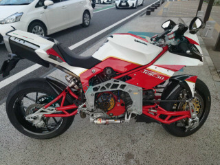
川崎のショップに引き取りに行きます。最寄りの駅から電車と徒歩で午後4時過ぎにショップに到着しました。

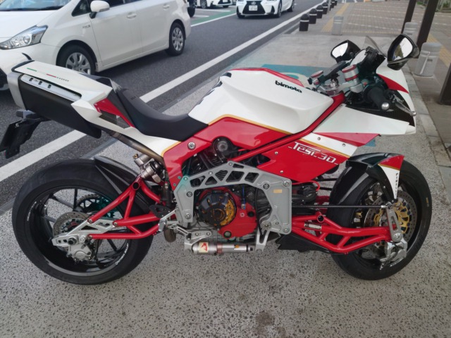
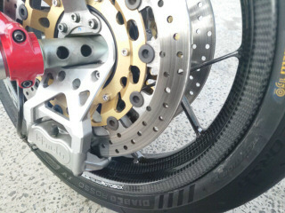
環八経由で関越に乗りました。環八はひどい渋滞でした。太ももが我慢出来ないくらい熱いです。関越に乗ってからは快適で、途中、三好SAで休憩しました。ロトボックスで取り回しがだいぶ軽くなりました。
6月6日
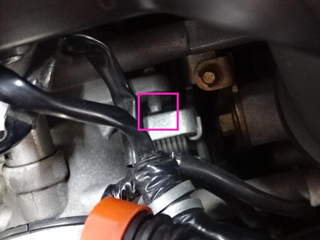
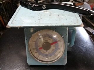
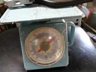
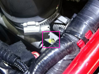
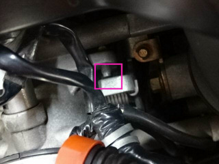
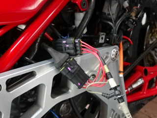
燃調が濃い件を調べていて、水平側のスロットルバルブのストッパのネジロックが剥がれて、回された跡が残っていました。垂直側のストッパは0.5mmほど隙間が開いています。この辺をいじってしまうとスロットルポジションセンサがズレて、本来はPCを接続してポジションセンサのリセットする必要があります。
全閉のスロットルポジションのセンサ値をメモしておきます。b−c間が2005Ω、a−c間が1301Ωでした。これでストッパをいじっても、元に戻せます。
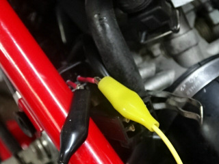
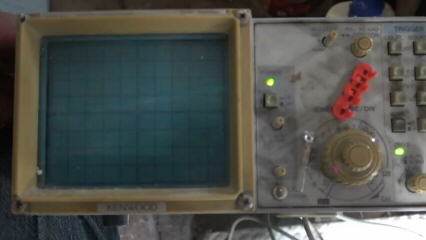
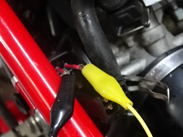
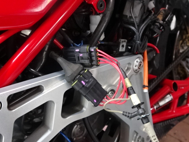
燃調が濃い件の続きです。O2センサの割り込みケーブルを作製しました。早速、センサの出力をオシロで調べます。
1Vのリッチ(燃料過多・酸素濃度低)と0.5V付近の理想値を行ったり来たりしています。本来は0Vのリーン(燃料希薄・酸素濃度高)間を交番するはずで、エンジンがかかっていない時は0Vを出力しているのでたぶん、センサは壊れていないです。リッチ側になる理由はフィードバックが掛かっていないからと思われます。ECUのセンサ入力が壊れていて常時リーンとして処理していると、こんな現象になると思われます(泣)。